Pages

Thursday 6 October 2022

ESP8266 Advanced HTTP Update from Windows IOT Core Server

 So I know the ESP8266 is old but I still like tinkering with them and just had to spend a two weeks (between work and life) starting anew project and trying to get the OTA (Over The Air) updating working as a starting point, rather than adding it as the last feature to my latest device.

I had this working before, but lost the original source code during the move to Sweden, so had to start from absolute scratch.

I figured I would document what actually needs to be done for this to work for my future self (and maybe someone out there also finds this interesting ;-).

Introduction

OTA stands for Over The Air. The idea here is that I do not need to plug my WiFi enabled device into the USB port, USB TTL Programmer etc to update the firmware. This is usefull for when you want to update the firmware of that device that is sitting by my front gate, to open, close and monitor the gate, while it's raining. I also don't have to climb into the ceiling of my house to go plug something into the controller that's managing some lighting, etc.

The server component here is a Windows IOT server running on a Raspberry Pi 3B that I also host css and js files on for some of the devices that have a web front-end. (A web site that manages my house is also running here so that every device does not need to be connected to some service out on the internet which I do not have control over.)

To get started you can have a look at: OTA Updates — ESP8266 Arduino Core 3.0.2 documentation (arduino-esp8266.readthedocs.io) Here the author show quite a few options of doing OTA which are much simpler. I wanted to use the advanced option for which he has examples in PHP. I wanted to run this on .net in C# though.

The Firmware Side

So here is my basic Arduino starter code for a simple ESP8266 project:

#include <WiFiManager.h>
#include "ESP8266httpUpdate.h"

const char* deviceName = "SomeDescriptiveName";// Device family name
const char* versionString = "0.1"; // Firmware version
const char* hwVersionString = "0.1"; // Hardware version
String eepBridgeURI = "192.168.1.103"; // Windows IOT server IP Address or URL
uint16_t eepBridgePort = 8084; // Windows IOT Server Port

void setup() {
  Serial.begin(115200);                        // Get Serial going
  delay(10);
  Serial.println("");
  Serial.println("");
  Serial.println(deviceName);
  Serial.print("- Hardware Version: ");
  Serial.println(hwVersionString);
  Serial.print("- Software Version: ");
  Serial.println(versionString);
  Serial.println("");

  Serial.println("Booting");

  WiFiManager wifiManager;                    // Connect to WiFi
  wifiManager.setConfigPortalTimeout(180);
  wifiManager.autoConnect("DeviceName","secureme");

  while (WiFi.waitForConnectResult() != WL_CONNECTED) {
    Serial.println("Connection Failed! Rebooting...");
    delay(5000);
    ESP.restart();
  }

  Serial.print("Connected to WiFi: ");
  Serial.println(WiFi.localIP());
  Serial.println();
  Serial.print("Checking for updates at ");
  String vString = deviceName;                // Here I build a string including
  vString += ".v";                            // device name, firmware version and
  vString += versionString;                   // hardware version.
  vString += "h";
  vString += hwVersionString;  
  Serial.print("http://");
  Serial.print(eepBridgeURI);
  Serial.print(":");
  Serial.print(eepBridgePort);
  Serial.println("/ota");
  Serial.print("with version string: ");
  Serial.println(vString);
// Here I execute the ESP8622 Http Update passing in the version string
  t_httpUpdate_return ret = ESPhttpUpdate.update(eepBridgeURI, eepBridgePort, "/ota", vString);
  switch(ret)
  {
    case HTTP_UPDATE_FAILED:
      Serial.println("- Update Failed.");
      Serial.print("  - Error (");
      Serial.print(ESPhttpUpdate.getLastError());
      Serial.print(") : ");
      Serial.println(ESPhttpUpdate.getLastErrorString());
      break;
    case HTTP_UPDATE_NO_UPDATES:
      Serial.println("- Up to date.");
      break;
    case HTTP_UPDATE_OK:
      Serial.println("- Update ok."); //may never be called
      break;
  }

  Serial.println();
  Serial.println("Configuring pins.");
 // Do other setup steps...
  Serial.println("Setup complete");
}

void loop() {
  // Do stuff...
}

Quick notes on the code above

I build quite a few different devices which all make use of the same OTA API.

  • Device Name: This tells the server side components which device is requesting an update.
  • Hardware Version: This allows me to deal with the same device family with different versions of hardware.
  • Firmware Version: This is the number I search on, on the server, and then return you the highest number available (If it's higher than the current version).
When you run the above code and monitor what is send to your server the following set of headers are delivered:
                User-Agent:ESP8266-http-Update
                Content-Length:0
                x-ESP8266-Chip-ID:55547542
                x-ESP8266-STA-MAC:18:FE:34:D7:DF:D6
                x-ESP8266-AP-MAC:1A:FE:34:D7:DF:D6
                x-ESP8266-free-space:598016
                x-ESP8266-sketch-size:362656
                x-ESP8266-sketch-md5:685ff5d9eeda8a0873c94b0f56d350e4
                x-ESP8266-chip-size:4194304
                x-ESP8266-sdk-version:2.2.2-dev(38a443e)
                x-ESP8266-mode:sketch
                x-ESP8266-version:Gineer.Home.Rainguage.v0.5h0.1

As you can see, the version string I pass through arives on the server in the x-ESP8266-version header.

Server Side

The code below is the OTA API controller for my ASP.Net Core Web App which is running on the Windows IOT server.
using Microsoft.AspNetCore.Http;
using Microsoft.AspNetCore.Mvc;
using Microsoft.Net.Http.Headers;
using System.Net;
using System.Net.Http;
using System.Text;

namespace Gineer.Home.Web.Controllers
{
    [Route("[controller]")]
    [ApiController]
    public class OTAController : ControllerBase
    {
        IHeaderDictionary headers;

        [HttpGet]
        public async Task<IActionResult> OTA()
        {
            headers = Request.Headers;

            // Here we do some very basic checks to see that it is an ESP8266 update request
            if (!checkHeader("User-Agent", "ESP8266-http-Update"))
            {
                return StatusCode((int)HttpStatusCode.Forbidden);
            }

            // Let's make sure the version string was actually sent through
            if (!checkHeader("x-ESP8266-version"))
            {
                return StatusCode((int)HttpStatusCode.Forbidden);
            }
            // Let's extract the full version string
            String DeviceVersionString = headers["x-ESP8266-version"];

            // Extract the device name and the current hardware and software versions
            // Example: DeviceName.v1.25h1.0
            Int32 VersionStringIndex = DeviceVersionString.IndexOf(".v");
            String DeviceName = DeviceVersionString.Substring(0, VersionStringIndex);
            String DeviceVersionRaw = DeviceVersionString.Substring(VersionStringIndex + 1);
            String[] VersionArray = DeviceVersionRaw.Substring(1).Split("h");
            Double SoftwareVersion = Double.Parse(VersionArray[0]);
            Double HardwareVersion = Double.Parse(VersionArray[1]);

            // Here we build a search pattern to find any available updates for this device and hardware version
            String[] files = new string[] { };
            if (HardwareVersion.ToString() == ((Int32)HardwareVersion).ToString())
            {
                files = Directory.GetFiles("c:\\firmware", DeviceName + ".*.*h" + HardwareVersion.ToString("0.0") + ".bin");
            }
            else
            {
                files = Directory.GetFiles("c:\\firmware", DeviceName + ".*.*h" + HardwareVersion.ToString() + ".bin");
            }

            // Here We get the latest version available
            String returnfilename = getHighestAvailableVersion(files, SoftwareVersion);
            if (returnfilename == String.Empty)
            {
                // If the list comes back empty, the device is already on the latest version
                return StatusCode((int)HttpStatusCode.NotModified);
            }

            // Read and return the newest firmware for this device
            var stream = System.IO.File.OpenRead(returnfilename);

            return new FileStreamResult(stream, "application/octet-stream");
        }

        // Get the highest version of available firmware files for this device
        private string getHighestAvailableVersion(string[] files, double softwareVersion)
        {
            double highestSoftwareVersion = 0;
            String filename = String.Empty;

            foreach (var file in files)
            {
                String tempfilename = file.Substring(file.LastIndexOf("\\")+1, file.Length - 5 - file.LastIndexOf("\\"));
                Int32 VersionStringIndex = tempfilename.IndexOf(".v");
                String DeviceVersionRaw = tempfilename.Substring(VersionStringIndex + 1);
                String[] VersionArray = DeviceVersionRaw.Substring(1).Split("h");
                Double SoftwareVersion = Double.Parse(VersionArray[0]);

                if (SoftwareVersion > highestSoftwareVersion)
                {
                    highestSoftwareVersion = SoftwareVersion;
                    filename = file;
                }
            }
            if (highestSoftwareVersion > softwareVersion)
            {
                return filename;
            }
            else
            {
                return String.Empty;
            }
        }

        // Check the headers provided
        private Boolean checkHeader(String name, String value = "")
        {
            // Does the required header exist?
            if (!Request.Headers.Keys.Any(k => k.ToLower() == name.ToLower()))
            {
                return false;
            }
            if (value.Length > 0)
            {
                // Does the header contain the required value?
                if (headers[name].ToString().ToLower() != value.ToLower())
                {
                    return false;
                }
            }
            return true;
        }
    }
}

Quick notes on the code above

On the Windows IOT server, I have a firmware folder called into which I simply copy the compiled bin files every time I create a new version.
  1. I simply open a powershell instance to the server
  2. Start the FTP Process
  3. Copy the new bin file to the firmware folder
  4. Stop the ftp process.
Now the new firmware is ready to go to any device that checks for an update.

Conclusion

Security

The above example does not contain any security, which you should always include in your implementation. There are a few easy examples like update password and MD5 hash checking, but I left those out of the example above for brevity. Make sure your server and your devices are secure.

Other options

In this example the device checks for an update every time it is turned on. I have other devices that contain a web front-end for which there is a button in the settings page that initiates the check for updates.

It's just the ESPhttpUpdate.update() method that must be executed to do the update.

ESP8266 Flash Size

Remember that the biggest firmware file you can send in this way has to be smaller than half your ESP's available flash storage.

By default, the arduino IDE set my ESP's Flash Size, to 1MB (FS:64KB OTA:~470KB), which aused my device to through an exception every time it tried to get a new firmware from the server.

Using the firmware at: Arduino/CheckFlashConfig.ino at master · esp8266/Arduino · GitHub to check, I confirmed that my device has 4MB of flash, so I set the Flash Size to 4MB (FS:1MB OTA:~1019KB).

After a hardwired upload, the OTA updates work perfectly.

That's it

I have now made sure this code (both firmware and serverside code) is nicely backed up (and even blogged here) for posterity.

I can now use the firmware above as a nice started template for anything ESP8266 which should require me to only fidle with my TTL RS232 cable (O, and let's not forget having to ground IO0 to initialise it into firmware upload mode) once for every new device. 

Tuesday 21 September 2021

Moving to Sweden from South Africa

So this post is nowhere near the normal topics on my blog, but thought it would be worth posting in case it helped someone else. If you are here for help with moving to Sweden, and you have an interest in anything to do with technology, electronics, robotics or similar, have a look at the other posts here.

Friday 28 July 2017

Wi-Fi Enabled bed lamp - Project to teach the kids

In today's world where school is all theory with very little reality to pin it to in our mental model, we decided to try and give some kids as many different experiences as we could as early as possible. Once they get to the theories taught in the classroom they will hopefully have some mental model to connect it with.

This is one of those projects.

The Wi-Fi enabled Bedlamp


4 Kids aged between 7 and 13 and their parents each built their own Bed side lamp. We started off with the woodwork. We encouraged them to do as much of the work themselves, even with the larger machinery (With good and careful adult supervision).
Some kids and dads while doing the woodwork.
The Circuit we built was relatively simple and consisted mostly of just an ESP01 (which has a total of two GPIO's), a relay, a linear voltage regulator (for the 3.3V supply) and a couple of passives, all soldered to some veroboard.

Functional Diagram showing main components
The button was connected to allow for in place programming. With Tx and Rx connected, if you powered the circuit on while holding down the button, the ESP8266 would boot into firmware mode, otherwise it would start-up normally.
Circuit diagram
We printed the image below out and everyone placed their pack of components into the vera board and soldered the bits themselves.
Vera/Strip board component layout
Mom and daughter sorting and placing components on their boards before soldering them.
Mom helping her daughter. Neither have ever built electronics before.
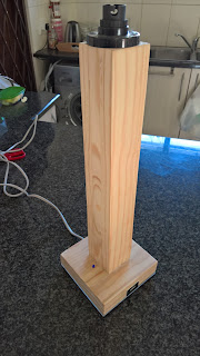
Below are some images of a finished lamp with a perspex/plexiglass bottom to show off the work.
Perspex/Plexiglass bottom cover to see the hard work.

We made use of a 5V USB charger, which was stripped of it's case and had the 5V rail tapped off to power our circuit. This provided a nice opportunity to integrate the original USB charger into the side of the lamp, where your phone will probably be during the night anyway, ;-)
USB charger on the side.
When the lamp is initially turned on in a new network, the lamp comes up as a WiFi access point. Connecting to it opens a web interface allowing you to search, configure and connect to your local Wi-Fi network. Once that is done, your Wi-Fi router should provide the lamp with its own IP address (You can easily find the new IP address by looking on your router configuration page.
Mobile phone UI when connecting to the lamp via Wi-Fi
We wired the relay up to be off while GPIO2 (Also connected to the LED on the module) was on so that it would shine through the clear plastic round bar used to press the power button. This made the on switch glow blue while the light is off. This makes it nice and easy to find the light switch at night.
Light Switch glows when the light is off.
The video below is a really short view of the basic operation of the finished lamp.


As always, I would love to hear your thoughts in the comments below.

Bill of Material

  • LM1117-3,3 3.3V Liear Voltage Regulator
  • 10µF capacitor
  • 100µF Capacitor
  • Momentary push tactile button
  • Mains rated relay with 5V actuator
  • 4 x 3K3Ω Resistor
  • 1N4001 Diode
  • BCM337 NPN transistor
  • ESP-01s ESP8266 module
  • Cheap 5V 1AMP USB charger

Firmware Source Code

/*
 * Copyright 2017 Gineer RnD
 * Redistribution and use in source and binary forms, with or without modification, are permitted provided that the following conditions are met:
 * 
 * 1. Redistributions of source code must retain the above copyright notice, this list of conditions and the following disclaimer.
 * 2. Redistributions in binary form must reproduce the above copyright notice, this list of conditions and the following disclaimer in the
 *    documentation and/or other materials provided with the distribution.
 * 
 * THIS SOFTWARE IS PROVIDED BY THE COPYRIGHT HOLDERS AND CONTRIBUTORS "AS IS" AND ANY EXPRESS OR IMPLIED WARRANTIES, INCLUDING, BUT NOT LIMITED
 * TO, THE IMPLIED WARRANTIES OF MERCHANTABILITY AND FITNESS FOR A PARTICULAR PURPOSE ARE DISCLAIMED. IN NO EVENT SHALL THE COPYRIGHT HOLDER OR
 * CONTRIBUTORS BE LIABLE FOR ANY DIRECT, INDIRECT, INCIDENTAL, SPECIAL, EXEMPLARY, OR CONSEQUENTIAL DAMAGES (INCLUDING, BUT NOT LIMITED TO,
 * PROCUREMENT OF SUBSTITUTE GOODS OR SERVICES; LOSS OF USE, DATA, OR PROFITS; OR BUSINESS INTERRUPTION) HOWEVER CAUSED AND ON ANY THEORY OF
 * LIABILITY, WHETHER IN CONTRACT, STRICT LIABILITY, OR TORT (INCLUDING NEGLIGENCE OR OTHERWISE) ARISING IN ANY WAY OUT OF THE USE OF THIS
 * SOFTWARE, EVEN IF ADVISED OF THE POSSIBILITY OF SUCH DAMAGE.
*/
// Relay control using the ESP8266 WiFi chip

// Import required libraries
#include <ESP8266WiFi.h>
#include <DNSServer.h>
#include <ESP8266WebServer.h>
#include <WiFiManager.h>

//Room Name
const String RoomName = "Switch";

//Response from Client
String request = "";

// The port to listen for incoming TCP connections 
#define LISTEN_PORT           80

// set pin numbers:
const int buttonPin = 0;    // the number of the pushbutton pin
const int relayPin = 2;      // the number of the SWITCH pin

int relayState = LOW;         // the current state of the output pin
int buttonState;             // the current reading from the input pin
int lastButtonState = LOW;   // the previous reading from the input pin

long lastDebounceTime = 0;  // the last time the output pin was toggled
long debounceDelay = 50;    // the debounce time; increase if the output flickers

// Create an instance of the server
WiFiServer server(LISTEN_PORT);
WiFiClient client;

void setup(void)
{  
   // Start Serial
   Serial.begin(115200);
   delay(10);
   Serial.println();
   Serial.println();
   Serial.println();
   Serial.println();

   //initialise WiFi Manager
   WiFiManager wifiManager;

   //first parameter is name of access point, second is the password
   wifiManager.autoConnect("GineerLamp", "secureme");

   pinMode(buttonPin, INPUT);
   pinMode(relayPin, OUTPUT);

   // set initial SWITCH state
   digitalWrite(relayPin, relayState);
  
   Serial.println("");
   Serial.println("WiFi connected");
  
   // Start the server
   server.begin();
   Serial.println("Server started");
  
   Serial.println("You can connect to this Switch at this URL:");
   Serial.print("http://");
   // Print the IP address
   Serial.print(WiFi.localIP());
   Serial.println("/");
  
}

void loop() {
  request = "";
  
  // Handle REST calls
  WiFiClient client = server.available();
  if (client) {
     Serial.println("User connected.");
     while(!client.available()){
          delay(1);
     }
     Serial.print("Request Received:");
     request = client.readStringUntil('\r\n');
     Serial.println(request);
     client.flush();
  }

    //process the request
    if (request.indexOf("/SWITCH=ON") != -1) {
       relayState = HIGH;
    }
    if (request.indexOf("/SWITCH=OFF") != -1) {
       relayState = LOW;
    }

   // read the state of the switch into a local variable:
   int reading = digitalRead(buttonPin);

   // If the switch changed, due to noise or pressing:
   if (reading != lastButtonState) {
     // reset the debouncing timer
     lastDebounceTime = millis();
   }

   if ((millis() - lastDebounceTime) > debounceDelay) {
     // whatever the reading is at, it's been there for longer
     // than the debounce delay, so take it as the actual current state:

     // if the button state has changed:
     if (reading != buttonState) {
       buttonState = reading;

       // only toggle the SWITCH if the new button state is HIGH
       if (buttonState == HIGH) {
         relayState = !relayState;
       }
     }
   }

   digitalWrite(relayPin, relayState);

   // save the reading.  Next time through the loop,
   // it'll be the lastButtonState:
   lastButtonState = reading;

  if (client) {
      client.println("HTTP/1.1 200 OK");
      client.println("Content-Type: text/html; charset=UTF-8");
      client.println("");
      client.print("<!DOCTYPE html><html><head><title>");
      client.print(RoomName);
      client.print(": Gineer.Home.SmartSwicth</title><style>body {background-color: black;color: white;text-align: center;}#switchSlider {display: inline-block;left: 28px;position: relative;border: 4px solid gray;width: 40px;height: 120px;vertical-align: central;}#switchToggle {display: inline-block;left: -30px;position: relative;border: 4px solid gray;width: 60px;height: 20px;vertical-align: central;}#switchSlider.off {background-color: silver;}#switchToggle.off {top: -20px;background-color: silver;}#switchSlider.on {background-color: yellow;}#switchToggle.on {top: -80px;background-color: yellow;}</style></head><body><h1>");
      client.print(RoomName);
      client.print("</h1><a href=\"/SWITCH=");
      if(relayState == HIGH)
      {
         client.print("OFF");
      }
      else
      {
         client.print("ON");
      }
      client.print("\" border=\"0\"><div class=\"");
      if(relayState == HIGH)
      {
         client.print("on");
      }
      else
      {
         client.print("Off");
      }
      client.print("\" id=\"switchSlider\"></div><div class=\"");
      if(relayState == HIGH)
      {
         client.print("on");
      }
      else
      {
         client.print("Off");
      }
      client.print("\" id=\"switchToggle\"></div></a><br /><br /><a href=\"/\">Refresh</a> <br /><br />Brought to you by <a href=\"http://www.gineer.co.za/\">Gineer R&D</a><p style=\"font-size: x-small;\">Rest: http://");
      client.print(WiFi.localIP());
      client.print("/SWITCH=ON or http://");
      client.print(WiFi.localIP());
      client.print("/SWITCH=OFF</p></body></html>");
      Serial.println("htmlsent");
   }
}

Friday 22 July 2016

Lab supply progress - Rectifier board redesign

I've finally made some progress with the power supply. After re-spinning a board and twice setting my diodes on fire, I now have a working first stage.

In the video below I give you a quick run through of my work and also show the inrush current limiting board and the regulator stage.


As I've mentioned before, this power supply will also be modular, but not only in the sense that each stage will be a separate board, but even at the board level parts are optional. This allows for you to build a bare bones analogue PSU through to a fully connected lab grade power supply.

Leave comments below. :-)


Sunday 17 July 2016

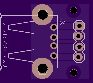
Open Source Hardware: USB-A Mounting board

while ago I tore down an old device (Can't remember if it was an old printer or something else) and found a neat little module that you could screw onto the side of a case to hold a USB-A port securely. Many designs have the USB port mounted on the main PCB but in many cases I want a USB port some distance from the main PCB which then makes it quite hard to mount it nicely.

This board, together with a quick and easy 3D printed housing, makes it a perfect solution (in my opinion anyway ;-) I've made the PCB available on thingiverse and the PCB available on OSHPark.


Get the PCB from OSHPark:

Order from OSH Park

Get the 3D Printed part from Thingiverse:

Gineer USB-a Female receptacle Case Mount

Monday 31 August 2015

3D Printer Upgrade

Over the weekend, right in the middle of a major project, my printer started acting up (as usual). One of the issues I experienced, for the first time ever, was that my drive pulleys for my uprights were slipping.


I opted for replacing them with off the shelf aluminium pulleys with 5mm belts. The next problem I had was how to tension the belts.


After a quick search online, I found some interesting and amazing belt tensioning techniques involving some 3d printed parts. These are all good and well except that they were all a bit of over-engineering.


With a non-working printer, I had some springs from the cables I were using before, some galvanised wire and a couple of tools. From the wire I quickly bent (using long nose pliers) some loops to connect the belt to the spring as shown in the diagram below.

I then looped the belt through them. Ensuring that the teeth mesh nicely, I added a small piece of plastic on both sides (to ensure the belt is not squashed sideways) and cable tied them together. Hooking the spring now supplies dynamic self-tensioning and it all works perfectly.


In most cases, simpler is better.

One potential downside to this approach could be the fact that the belt makes such a tight turn over the loops which could be a failure point when the belt starts to perish. I'll keep you posted if that happens.


Monday 22 June 2015

Lab Power Supply: OpAmps, Analogue Control and Digital Monitoring

I've progressed to the point where I think the second stage of the Lab Power supply is probably ready for an initial board to be made.
In this video I go through the OpAmp design, the digital monitoring, Linear control and the design of the shunt resistors in the second of three main boards in the system.

Might be time to have at least the Raw Power board manufactured so that I can progress to a stage where I can start testing the design of the second stage.